
FM200 is a firestop unit. It is a gas based system. Its purpose is to prevent fire. It works quickly during a fire. The system is fast and secure. Its use is increasing primarily in the United Arab Emirates. It appears to be the central data room and mall. It’s set up everywhere. Wiring the panel is easy. Just follow the plan.
The FM200’s panel is a smart box. This is the central light and bell. When the fire signal comes, the light turns on. The bell rings on the firetime man. The sensor has alerted us at this time. The system detects fire by heat. The sensor also detects smoke. All parts work together. Wiring is known to all. Each point has its own role.
Necessary tools and materials
- Wire cutter for cutting wire
- A test tool for testing strength
- Tape to cover the wire
- To make drill holes
- To fit the screw device
- Box fitting tool
- Cap for wire end cover
- You are an alarm test tool.
Step wise wiring tariqa
Clean the area before installing the panel. Mark the wall. Drill the holes and fit the screws. Place the box directly on the wall. Connect the power cord first. Red wire power is hot. The black wire is neutral. Both wires are connected to the panel. Hold the wire with a clip. Test the line with a power tool.
Sensor wiring method
A smoke sensor is installed on the roof above. The heat sensor seems to be a false Wallman. The manual box is on the lower wall. The vine is mounted on the central wall. All these are connected to the wire panel. The sensor line is different. The wire has to be kept clean. Use of clip and tape is essential.
Manual point setup
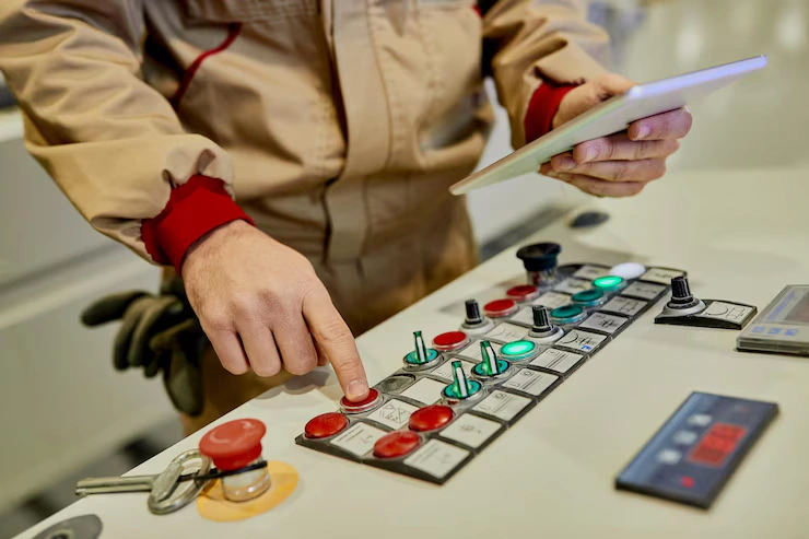
The red hota is the manual point. This push gives a warning. The manual is written from the panel line. Wire connection from both points. The signal is checked by a push test. Press Log on Firetime. His voice is raised.
Alarm bell setup
The bell serves as a fire alert. A bell rings when the panel sends a signal. Place the bell near the hall and ceiling. The wire extends from the vine to the panel. Use a clip to hold the wire. Sound is checked by test push. The bell fuse also has to be checked.
Gas release button
This button is green or white. It is used only during fire. Looks close to the panel. This activates the button lock. Its wire goes directly to the panel. This sends a signal to release the gas. Never push the test man.
Solenoid valve setup
Solenoid is a gas gate that opens only when a fire signal is received. This valve allows the flow of gas during a fire. Its wire is connected to the solenoid port of the panel. The wire is red and black with the red line for power and the black line for ground. The wire has to be held firmly with a clip and tape so that the line does not short out. The solenoid box has to be screwed to the wall. This is done with a valve test tool. Place the test tool on the valve point and read the signal. When voltage comes from the tool, the valve clicks.
A click means the gate is ready. If there is no click, then check the wire and fuse. The fuse panel is working which is tested with the tool. If the fuse is dead, install a new fuse. The valve light also flashes when the signal is activated. The solenoid cover should be tight to prevent dust from entering. This test is to be done only at certain times. How to do this test in normal time? The gas line is opened by a signal from the valve. The panel sets the delay time so that the system operates automatically. It is an important part of the valve insert system.
Gas Test Disable button
This button is only used during fire test drills. Its purpose is to contain the gas while the fire test is taking place. It is mounted on the wall near the button panel. Button color is white or green. This wire is connected to the disabled port on the panel. When the button is pressed, the panel light turns on. A flashing light means the signal is OK. The bell also makes a soft sound when pressed. The button should be placed inside the lock box so that no one can press it. This button is normally off.
It is only active during the test drill. The signal from the button is sent to the relay board of the panel. The relay causes both the light and the valve to close. The signal from this button is also checked with a test tool. The press time should be short and the brightness of the light should be stable. If the flash is slow, check the fuse. This button is an essential part of UAE’s main fire drill. Monthly testing should be done at each site to ensure system functionality.
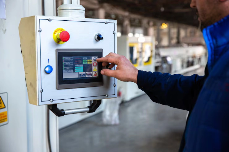
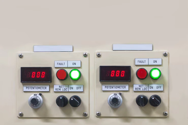
Display unit setup
The function of the display is to show the fire signal on the panel. This light and buzz alerts you. When there is a fire, the screen shows a red light and a sound. The green light stays on during normal hours. The display unit is mounted on the wall at eye level with screws. Its wire is connected to the data port of the panel. The wire color is black and blue. The wire must be secured with clips and tape. The display is tested with light and sound.
Inside the display unit is an LED light. If the light goes out, the unit has to be replaced. The new unit should have the same model. The display cover is transparent which should be clean. The screen dims when dusty. The display should be cleaned every week. The log screen is read during the test so it is important to keep it clean and active. The display’s role is to show warnings and log information.
Power supply setup
The panel needs the right power. Electricity has to be taken from the main line. Fuses are to be used in the mains. The battery is also in the main panel. When the light goes off, the battery comes back to life. Check the line with a power test tool. There is also a battery test button.
Wiring Tips UAE Mains
- Use the color code
- Hold the wire door against the sharp edge
- Clean the wire inside the panel
- Label each line.
- Draw the wires according to the map
Wiring faults and problems
A beep means an error. The wire may be loose. The sensor may be dead. Power may be reduced. Test for heat or smoke. The ringing sound may be reduced. If the display is dead, check the fuse.
Effect of UAE Fire Code
Rules of SIRA have to be followed. Only the cert log system is installed. Each wire must conform to the code. Fire test is conducted every year. People have to be trained. The setup plan has been approved by SIRA.
Engineer Tips for UAE
- Consider the wire map
- Sensor test search
- Check the bell sound
- Press the button.
- Learn to use a drill.
- Be sure to read the display
FM200 setup plan
Panel wires are important on all sides. The sensor is on the top and side. The bull’s-eye region appears to be important. The button is on the lower wall. The power cord comes from the edge of the wall. Follow the map.
How to understand a wiring diagram
All parts of the box are moving upwards. The wire point should be clean. The sensor and bell are connected directly to the panel. The manual and gas buttons are shown on separate lines in the main. The display is on a different port.
Conclusion
The smoke sensor test can be done with cloth. Test the temperature sensor with the light on. To test by pushing the manual. Check the bell sound. Read the display. Check each section. The light should flash. The voice should be loud. The power light should be green.
Temperatures are rising in the UAE. The possibility of fire also increases. FM200 works fast. Fire cannot be stopped without water. Data is protected. The machine is safe. Both Lab and Mall are safe hotels. The system reacts quickly.
The Wiring setup of the FM200 panel is simple. Must have basic tools and plans. Follow each step. Tests provide evidence of system effectiveness. Safety rules are paramount. FM200 in UAE is the best option. Every engineer should have this setup. This guide will help you.